Raspberry Pi 4 Model B Development Kit
Introduction
The Raspberry Pi 4B is powered by the Broadcom BCM2711, a quad-core Cortex-A72 (ARM v8) 64-bit SoC clocked at 1.8GHz. It offers significant performance improvements over previous models, making it an ideal choice for projects requiring higher processing power. The board also supports a variety of peripherals including high-speed USB 3.0, dual HDMI outputs, and Gigabit Ethernet.
The onboard wireless capabilities (Wi-Fi and Bluetooth) and the Raspberry Pi’s standard 40-pin GPIO header ensure a wide range of expansion possibilities. It’s an excellent platform for IoT, media centers, and general-purpose computing projects.
The Oniro Project supports the Raspberry Pi 4B, and the following features have been verified to be working:
- GPU graphical acceleration
- USB camera support
- HDMI output
- Touch input
- Mouse input
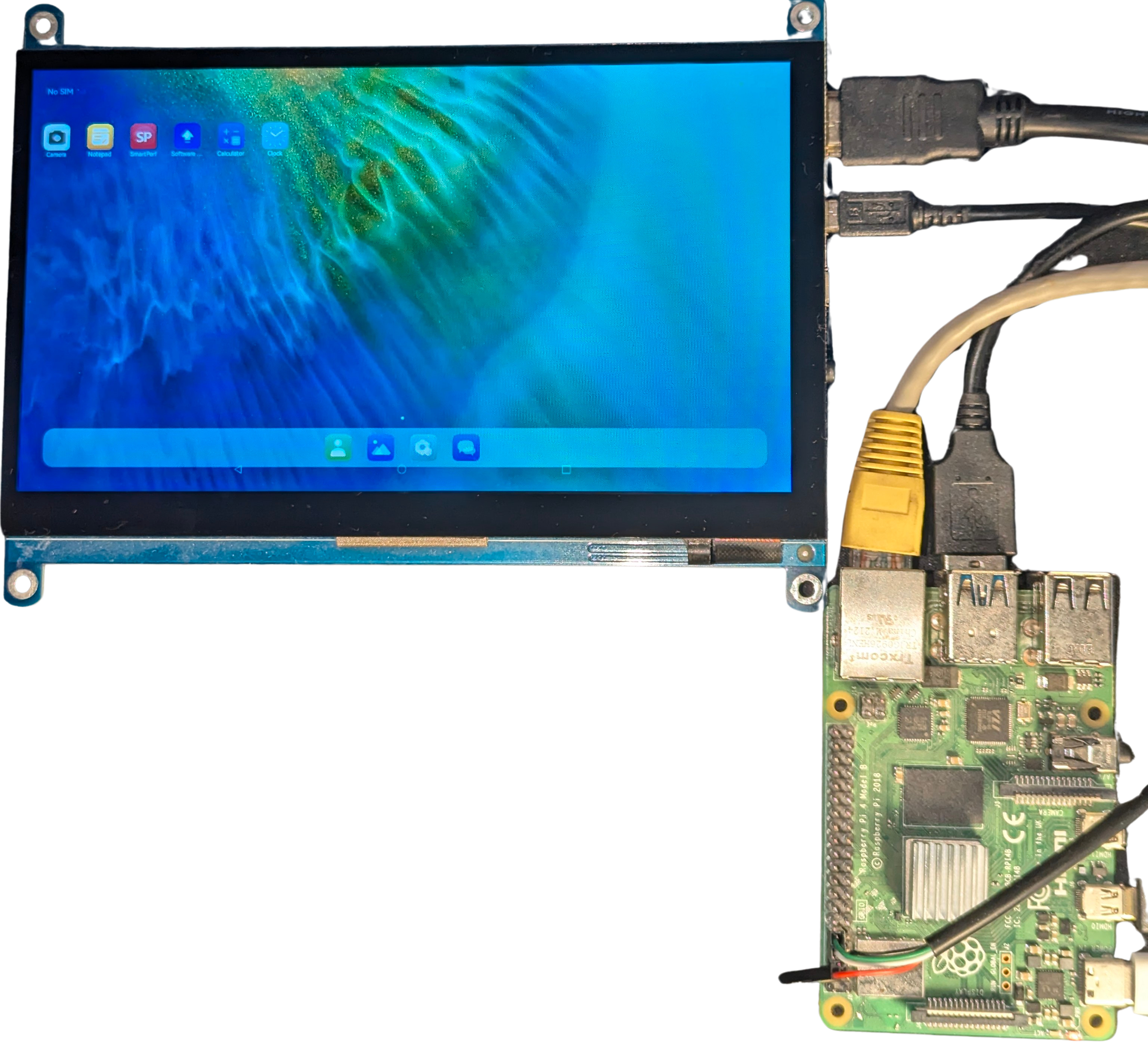
Oniro on Raspberry Pi 4b and waveshare 7inch touch screen
Specification
Development Board Specification
| Category | Specification |
|---|---|
| SOC Model | Broadcom BCM2711 |
| CPU Architecture | Quad-core Cortex-A72 (ARM v8) 64-bit SoC @ 1.8GHz |
| GPU | OpenGL ES 3.1, Vulkan 1.0 |
| Wireless | 2.4 GHz and 5.0 GHz IEEE 802.11ac wireless, Bluetooth 5.0, BLE |
| Ethernet | Gigabit Ethernet |
| RAM | 1GB, 2GB, 4GB, or 8GB LPDDR4-3200 SDRAM (depending on model) |
| Video Decoding | H.265 (4kp60 decode), H.264 (1080p60 decode, 1080p30 encode) |
| Power Input | 5V DC via USB-C connector (minimum 3A) or GPIO header |
| Operating Temperature | 0 – 50 degrees C ambient |
| Storage | Micro-SD card slot for OS and data storage |
| Operating Systems | Supports various Linux distributions, including Oniro |
Expansion Board Specification
| Category | Specification |
|---|---|
| HDMI | 2x micro-HDMI (supports 4K at 60fps output) |
| MIPI | 2-lane MIPI DSI display port, 2-lane MIPI CSI camera port |
| USB | 2x USB 3.0 ports, 2x USB 2.0 ports |
| GPIO | 40-pin GPIO header (fully backwards compatible) |
| Audio/Video | 4-pole stereo audio and composite video port |
| PoE | Power over Ethernet (requires separate PoE HAT) |
Building
After completing the steps in the quick build documentation to set up your build environment, proceed with the following steps to compile and build the system image for the Raspberry Pi 4B.
Step 1: Prepare the Build Environment
Run the following script to apply system patches:
chmod 777 device/board/rpi/system_patch/system_patch.sh
./device/board/rpi/system_patch/system_patch.sh
Step 2: Compile the System Image
Execute the following command to build the system image:
./build.sh --product-name rpi4 --ccache
Step 3: Package the System Image
Once the compilation is complete, package the image using this command:
./build.sh --product-name rpi4 --ccache --build-target rpi_image
The compiled files will be archived in the out/rpi4/ directory, and the final image will be located at:
out/rpi4/packages/phone/images/
Flashing
To flash the image, follow these steps in a Linux environment:
Step 1: Insert the SD Card
Insert your SD card (at least 16GB) into the card reader and connect it to your computer.
Step 2: Identify the Device
Run the following command to list all connected devices:
lsblk
Locate your SD card by identifying its size in the list. The device name will be something like /dev/sdX, where X is a letter such as b, c, etc. For example, it could be /dev/sdc.
Step 3: Unmount the Device
If the device has any mounted partitions, you must unmount them before flashing the image. For example, if your device is /dev/sdc, run the following command to unmount all partitions:
sudo umount /dev/sdc*
Step 4: Flash the Image
Now, use the dd command to write the image file to the SD card. Replace /dev/sdX with the appropriate device name (e.g., /dev/sdc), and run the following command:
sudo dd if=out/rpi4/packages/phone/images/rpi_image.img of=/dev/sdX bs=4M conv=fsync status=progress
This will begin the flashing process. The status=progress option will display the progress of the flashing process.
Step 5: Eject the SD Card
Once the flashing is complete, safely eject the SD card using the following command:
sudo eject /dev/sdX
You can now insert the SD card into your Raspberry Pi 4B for use.
Debugging
1. Connecting via Serial
To debug via serial, use the following pin configuration:
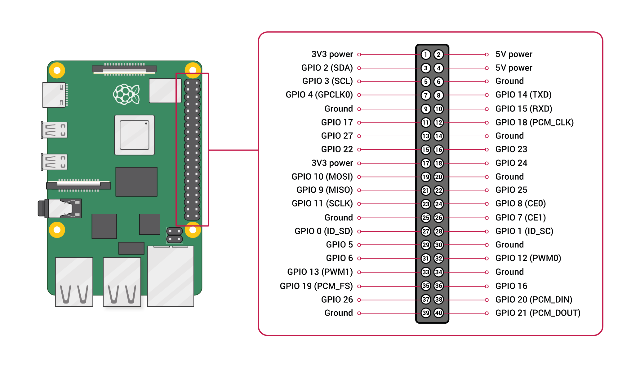
Connect the pins as shown in the diagram (Pins 6, 8, and 10). Then, use the following Minicom command to establish the serial connection:
sudo minicom --device /dev/ttyUSB0 --baudrate 115200
Make sure to replace /dev/ttyUSB0 with the appropriate serial port for your setup.
Tip: After establishing the serial connection, you will have access to the device’s shell. If the device is connected to a network, you can retrieve the IP address by running the ifconfig command. This will be useful for the next section on “Using the HDC Tool” to connect to the device over the network.
2. Using the HDC Tool
The HDC tool can be used for various debugging tasks. To connect, first connect the device via Ethernet to obtain the IP address, and then run the following command:
hdc tconn <device-ip>:5555
You should see Connect OK if the connection is successful.
Here are some useful HDC commands:
hdc shell: Opens a shell to the device.hdc file send {local_path} {device_path}: Sends a file from your local system to the device.hdc file recv {device_path} {local_path}: Receives a file from the device.hdc install <filename.hap>: Installs a.happackage on the device.