HiHope HH-SCDAYU200 Development Kit
Introduction
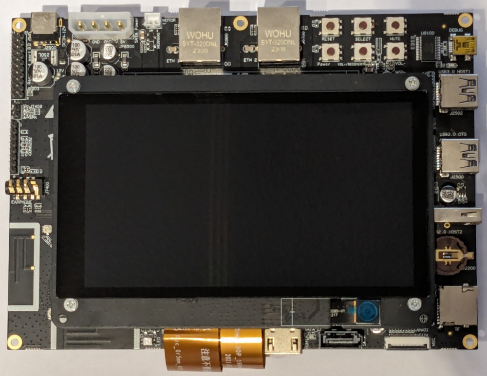
Based on the Rockchip RK3568, this development kit integrates advanced features such as a dual-core architecture GPU and a high-performance NPU. Complemented by an onboard quad-core 64-bit Cortex-A55 processor which has a frequency of up to 2.0GHz, it ensures robust performance.
The rich set of peripherals ranges from Bluetooth and Wi-Fi to audio, video, camera and a variety of Bosch Sensortec sensors.
The expansion board offers rich expansion interfaces, and supports a variety of video input and output interfaces suited for applications with rich user interface requirements.
It is also equipped with dual Gigabit adaptive RJ45 Ethernet ports, which can meet the needs of NVR, industrial gateway and other multi-network port products.
Specification
Development Board Specification
| Category | Specification |
|---|---|
| SOC Model | Rockchip RK3568 |
| CPU Architecture | Quad-core Cortex-A55 up to 2.0GHz |
| GPU | Mali-G52 GPU |
| Supported APIs | OpenGL ES 1.1/2.0/3.2, OpenCL 2.0, Vulkan 1.1 |
| Video Decoding | Supports 4K at 60fps H.265/H.264/VP9 video decoding |
| Video Encoding | Supports 1080P at 100fps H.265/H.264 video encoding |
| NPU Performance | 0.8TOPs |
| Supported Operations | INT8, INT16, FP16 operations |
| RAM | 2/4GB LPDDR4/LPDDR4x, running at 1600MHz |
| Storage | 16/32 GB |
| Power Input | DC 12V/2A |
| Operating Systems | OpenHarmony |
| Connector Type | SODIMM 314P (MXM 3.0) |
Expansion Board Specification
| Category | Specification |
|---|---|
| HDMI | 1x HDMI2.0(Type-A), supports 4K at 60fps output |
| MIPI | 2x MIPI interface, supports 1920x1080 at 60fps output |
| eDP Interface | 1x eDP interface, supports 2K at 60fps output |
| I2S/TDM/PDM | 1x 8 channel I2S/TDM/PDM |
| Ethernet | 2x GMAC(10/100/1000M) |
| SDIO | Supports Wi-Fi 5G/2.5G, BT4.2 |
| Camera Interface | MIPI-CSI2, 1x4-lane/2x2-lane at 2.5Gbps/lane |
| USB | 1x USB2.0 Host, Type-A; 1x USB3.0 Host, Type-A; 1x USB3.0 OTG |
| M.2 Interface | 4G LTE Module |
| PCIe | 1x 2 Lanes PCIe3.0 Connector (RC Mode) |
| SATA | 1x SATA3.0 Connector |
| SDMMC | 1x Micro SD Card3.0 |
| Buttons | 1x Vol+/Recovery; 1x Reset; 1x Power; 1x Vol-; 1x Mute |
| RTC | 1x RTC |
| Infrared | 1x IR |
| LEDs | 3x LED |
| Sensors | Bosch Sensortec BMA456, BMI270 and BMP581 |
| Fan | 1x Fan |
Building
To build Eclipse Oniro for this board the normal quick build procedure has to be used to fetch the needed source code and environment.
During the build step, inside the Docker instance, the target device for the build has to be set to rk3568.
./build.sh --product-name rk3568 --ccache
Flashing
To begin, connect the board to your computer as outlined in the HiHope DAYU200 documentation. Use the USB-C and mini-USB cables included in the kit to connect to the USB 3.0 OTG port and the mini-USB DEBUG port, respectively.
We have different steps for a standalone Linux system and for Windows systems with built-in WSL.
In Standalone Linux System
Power on the device by attaching the power cable. Upon successful connection, your serial console should display output similar to:
Bus 002 Device 009: ID 2207:5000 Fuzhou Rockchip Electronics Company "HDC Device"
...
Bus 001 Device 069: ID 0403:6001 Future Technology Devices International, Ltd FT232 Serial (UART) IC
Download the flash.py flashing tool from Gitee using the following commands:
git clone https://gitee.com/hihope_iot/docs.git hihope_iot_docs
mkdir flash && cp -r hihope_iot_docs/HiHope_DAYU200/烧写工具及指南/linux/* flash/
chmod +x flash/flash.py flash/bin/flash.x86_64
To ensure proper device recognition, install the udev rule:
sudo cp flash/etc/udev/rules.d/85-rk3568.rules /etc/udev/rules.d/85-rk3568.rules
Then, either reload udev rules or reboot your system:
udevadm control --reload-rules
After this setup, running flash/flash.py -q should produce the following output, indicating readiness:
maskrom
To enable programming mode on the device, perform the following steps:
- Press and hold
VOL/RECOVERYthenRESETbuttons. - Release
RESETbutton.
Confirm the mode by running lsusb, which should show:
...
Bus 001 Device 070: ID 2207:350a Fuzhou Rockchip Electronics Company USB download gadget
...

$ flash/flash.py -q
loader
Once the above steps are completed successfully, you can proceed to flash the board:
flash/flash.py -a -i ./out/rk3568/packages/phone/images
Connecting to serial console
To read the serial output, ensure the board is correctly connected and powered on. The default baud rate for the HH-SCDAYU200 board is 1500000. You can use minicom or a similar serial terminal:
minicom -D /dev/ttyUSB0 -b 1500000
Windows System with built-in WSL
Power on the device by attaching the power cable. Upon successful connection, type lsusb on WSL your serial console will display output similar to:
Bus 001 Device 001: ID 1d6b:0002 Linux Foundation 2.0 root hub
Bus 002 Device 001: ID 1d6b:0003 Linux Foundation 3.0 root hub
It’s not connected yet, but don’t worry.
Download the flash.py flashing tool from Gitee using the following commands on your WSL:
git clone https://gitee.com/hihope_iot/docs.git hihope_iot_docs
mkdir flash && cp -r hihope_iot_docs/HiHope_DAYU200/烧写工具及指南/linux/* flash/
chmod +x flash/flash.py flash/bin/flash.x86_64
To ensure proper device recognition, install the udev rule:
sudo cp flash/etc/udev/rules.d/85-rk3568.rules /etc/udev/rules.d/85-rk3568.rules
Then, either reload udev rules or reboot your system:
sudo udevadm control --reload-rules
Then, we need to attach USB devices from Windows using Windows PowerShell to virtual Linux environment. Type usbipd list with output the following result, find busid for which device named “HDC Device”.
Connected:
BUSID  VID:PID    DEVICE                                                        STATE
1-2    24ae:185a  USB Input Device                                              Not shared
1-8    174f:2435  Integrated Camera                                             Not shared
1-9    06cb:00bd  Synaptics UWP WBDI                                            Not shared
1-14   8087:0029  Intel(R) Wireless Bluetooth(R)                                Not shared
1-17   2207:5000  "HDC Device"                                                  Shared
In our case, we need take busid 1-17.
Note
If the status of HDC Device is Not shared, type
usbpid bind --busid 1-17, in above case the device busid is 1-17, change it to adjust your case if necessary.After re-running command
usbipd list, you will find the device status changed intoShared.
Then we need to attach the device to wsl using command usbipd attach --wsl --busid 1-17, the output should be like the following, wait until attach process finishes:
usbipd: info: Using WSL distribution 'Ubuntu' to attach; the device will be available in all WSL 2 distributions.
usbipd: info: Detected networking mode 'nat'.
usbipd: info: Using IP address 172.24.144.1 to reach the host.
Note
If you are not sure about if the device had been attached already, detach it first using command
usbipd detach --busid 1-17
After this setup, running flash/flash.py -q should produce the following output, indicating readiness:
maskrom
Note
If the output is
none, try to re-run detach and attach procedures above, you can also check your device connection details usingdmesg | tail -n 50command on WSL.If still not working, try to change a cable, switch to connect another port on your PC or keep your board screen unlocked.
To enable programming mode on the device, perform the following steps:
- Press and hold
VOL/RECOVERYthenRESETbuttons. - Release
RESETbutton.
When your run flash/flash.py -q again, you will find the output is none again.
Open Windows PowerShell again and type usbipd list, the output will be like the following:
Connected:
BUSID  VID:PID    DEVICE                                                        STATE
1-1    24ae:185a  USB Input Device                                              Not shared
1-2    2207:350a  USB download gadget                                           Not shared
1-8    174f:2435  Integrated Camera                                             Not shared
1-9    06cb:00bd  Synaptics UWP WBDI                                            Not shared
1-14   8087:0029  Intel(R) Wireless Bluetooth(R)                                Not shared
Find the busid for device which named ‘USB download gadget’, in our case it is 1-2. Bind it first usbipd bind --busid 1-2, it requires to run the Windows PowerShell as administrator.
Then attach it to WSL, run usbipd attach --wsl --busid 1-2.
After that, switch to WSL and run flash/flash.py -q again you will find the output is loader, which means the device is under development mode now.
Once the above steps are completed successfully, you can proceed to flash the board:
flash/flash.py -a -i ./out/rk3568/packages/phone/images
Connecting to serial console
To read the serial output, ensure the board is correctly connected and powered on. The default baud rate for the HH-SCDAYU200 board is 1500000. You can use minicom or a similar serial terminal:
minicom -D /dev/ttyUSB0 -b 1500000
Reference
The original specification and some hardware description comes form the original (Chinese) HiHope documentation published on Gitee.
More details and purchase options can be found at the manufactures product page.